TLDR version
If the battery in your 1st-generation Jetforce pack is dead, then you may be able to rebuild it with new cells. The repair requires some familiarity with electronics and soldering skill. It took me a couple of hours and cost about $50 in parts.
However, keep in mind that you're replacing a tested, certified, reliable part with a sketchy, homemade version. And given that this battery will power a device intended to save your life, it should be obvious that you're taking a significant risk.
Background
After several years without touring, I pulled my Black Diamond Saga 40 Jetforce avalanche airbag backpack out of storage, and plugged it in to charge. Lots of flashing lights, mostly red, but the thing wouldn't charge. I tried different chargers on several different occasions, disconnected and reconnected the battery. No go.
In retrospect, this is not too surprising, as I know that lithium ion batteries don't like being left in a fully-discharged state. On the other hand, this is outdoor gear, which I'm accustomed to sticking in a box and just pulling out years later without any problems. My tent still works, even if I've not used it in a long while.
The manual does include detailed sections on "Care and Maintenance", "Storage and Transport", and "Inspection, Retirement and Lifespan", that describe keeping battery partially charged and at moderate temperature. However, these are buried in the fine print. Given the critical nature of these precautions, I feel that they should be much more forcefully and conspicuously communicated.
There's all sorts of alarming content in the manual, including this text: "The typical estimated lifespan of your replaceable Lithium-Ion battery is three to five years. All Lithium-Ion batteries deteriorate with age." Ouch. That's pretty disappointing for a product that costs in excess of $1000.
Another part worth noting is the word "replaceable". I don't know if, or for how long BD sold replacement batteries, but certainly they are no longer available. The Saga 40 is a 'first generation' Jetforce pack (mine was purchased in 2016) so is about seven years old at the time of writing.
Replacement batteries for 2nd generation Jetforce packs are currently available, but that doesn't help me any.
Response from BD customer service was essentially "I'm afraid you're out of luck". This was understandable, but very disappointing, so I decided to see what I could do to help myself.
Note: I did find a Japanese website selling what appears to be 11490 batteries with cells of different capacities. This might be worth a shot if you don't have the skills/time/appetite to rebuild your original battery.
Tools
Here's what I used:
- Phillips head screwdriver (to disconnect battery)
- Torx T9 screwdriver (to dismantle battery)
- Soldering equipment:
- Soldering iron, something fairly powerful. I used a 65 W iron.
- Solder removal pump or braid (to de-solder battery terminals)
- Solder
- Wire cutters
- If you don't have the above, try this soldering kit (~$20 on Amazon)
- Replacement cells. See below.
- Nickel connecting tabs. See below.
Dismantling the Battery
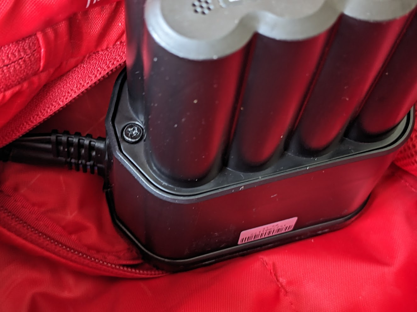
The battery is located in a zippered compartment at bottom of the main backpack compartment.
The battery module unscrews from the pack using two Phillips-head screws.
My battery says "Made in Poland". I gather that others were assembled in Germany.
To open up the battery module itself, you'll need a Torx T9 screwdriver. After unscrewing the four T9 screws on the battery lid, you can pull off the bottom shell.
At this point, it was clear that many of the individual cells in my battery were degraded, with obvious corrosion around the contacts, and blistering along the cylindrical exterior. No big surprise, then, that the battery was refusing to charge.
Unscrew two more T9 screws (silver) to release the the top plastic cover from the PCB.
To remove the PCB from the battery assembly, you'll need to de-solder the two terminal contacts. I used a solder sucker to remove the excess solder and wiggle the terminals loose. I didn't see anything close to the terminals that looked easy to damage, but maybe I was just lucky...
With the battery terminals loose, you also have to disconnect the white connector in order to remove the PCB. The naked battery assembly looks like this:
Colored wires run from the white connector to the join between each pair of cells, so I assume this is to assess the health of individual cells. e.g. to confirm that the potential difference across each cell is within tolerance. The two black wires feed into a cavity in the middle of the battery back, and terminate in a blob. I assume this is a thermocouple to measure battery temperature.
There is a card-like insulating sheet between the battery assembly and the PCB. I wasn't able to remove it without tearing it, but I imagine it's possible to do so if you're more careful than I was!
My battery showed a shocking amount of corrosion.
To break up the battery assembly, first remove two more T9 screws (black), one on the top side, one underneath. You may need to dig out and part the colored wires from the underside to access the second screw.
Next you need to remove the nickel strips that are spot-welded between each cell, and also the monitoring wires that connect to them. This is the point of no return, as the spot welds are strong, and there's really no way to remove the connecting strips without destroying them. But if your battery back is non-functional, what do you have to lose?
BTW, I suggest you take some photos to record the location of the colored battery monitor wires. It's possible that different revisions have different color schemes, so you should have some reference of what color wires go where, just in case my photos don't match yours.
Then you can gently pry apart the two pieces of the black plastic cage holding the individual cells.
The cells in my battery are Molicell IHR-18650C. These don't seem to be available anymore, but the
specifications are still available. These are 7.4 Wh (2000 mAh) 20 A rated.
Replacement Cells
Despite the temptation to replace these cells with "newer, better" versions, I was concerned that different, higher capacity cells would not follow the same charge/discharge characteristics, and that different cells might cause the battery health monitor to decide that the cells were defective and refuse to operate.
I ordered Molicell INR-18650-P28A cells as replacements. These are slightly higher capacity: 10.3 Wh (2800 mAh). I'm not sure whether this matters much. What
does matter is that they are rated for high current discharge, 35 A max (
specifications). You definitely need cells that can handle the high power draw when the fan is running and airbag inflating.
I ordered from
1850BatteryStore, and eight cells cost about $32 USD. At the same time, I also ordered some
8 mm nickel tabs for the cell interconnects. These weren't a perfect match to the tabs I'd just destroyed -- they needed to be cut down in length a little -- but they were close enough.
Rebuilding the Battery
If you've done any tinkering with electronics, this is all pretty much as you'd expect. I'm going to walk through it in agonizing detail, but feel free to skip ahead!
I started by roughening up the contacts of each cell with some sandpaper, and then "tinning" the contacts with solder, trying to do this as rapidly as possible to avoid damaging the cells by overheating them.
If I were to do this again, I think I might order cells that already have tabs spot-welded to their terminals (
example). I don't know how easy it is to damage Li-ion cells with a soldering iron, but this was the part of the whole process that made me the most nervous.
Then I reassembled the plastic cage around the new cells. Make sure to do this before you apply the nickel tabs! Also pay close attention to make sure you alternate up/down orientation of the cells, matching the original polarity,
I also tinned each of the nickel connecting tabs. I trimmed them to the right length, roughened each end, then put a blob of solder on the rough patch. I put the tab, solder-side-down, into position, and pressed down hard with the tip of the soldering iron until I felt the solder melt underneath the tab. Then I removed the soldering iron, but kept applying downward pressure with tweezers to hold the tab in place until the solder solidified.
On the underside of the battery pack, each of the connecting tabs go lengthwise. On top, it's a little more complicated. I bent the terminal tabs upward, and trimmed the ends to make them pointy to make it easier to feed them through the holes in the PCB.
Next it was time to reattach the battery monitor wires. I trimmed off as much of the original connector as I could, and again tinned the wires to maximize the integrity of the solder joint. Refer to your photos to ensure that you reconnect the right colored wire in the right place.
The result wasn't pretty. I used a small screwdriver to pry at each of the joints to see if they could easily be dislodged. Everything seemed acceptably solid. [Note: this is a notoriously unreliable way to assess the quality of a solder joint. See discussion about safety/reliability below.]
Finally, insert the insulating sheet into place, and feed the temperature sensor through the hole into the middle of the battery pack.
Now you need to reconnect the PCB. I used braid to remove as much solder as possible from the underside, so that there was an open hole through which to feed the tabs. Even so, I still needed to melt the solder on the upper side a bit more to get them to jiggle through completely. When both tabs are properly located, solder them in place. Make sure to use a good amount of solder, and inspect the joint carefully. These connections need to carry a high current!
Once that's done, you can trim off the excess length on the tabs, and do some measurement with a multimeter. I checked voltage across each cell to confirm they were all similar.
Finally, reattach the battery lid to the PCB (two silver T9 screws), reapply foam spacer to base, slide the pack into the bottom shell, and screw closed (four black T9 screws). Reattach the battery to pack (two black Phillips head screws).
Moment of Truth
Cross your fingers, and push the power button.
I got an instant red light and felt sick to my stomach. But then I realized I just probably needed to charge the battery. So I plugged in the charger and left the pack charging overnight.
Next morning, I was elated to see that I had four blue LED's lit. I disconnected the charger and tried the power button again. Great success! The pack completed its self-check and did the signature fan blast. Better still, a yank on the handle and the airbag inflated!
Not that I'd ever doubted for a moment that it would, of course. <cough>

Caveats
Above, I've attempted to describe how to resurrect your Gen1 Jetforce battery.
Now I feel obliged to explain why you shouldn't do this.
An avalanche airbag is a life saving device, and it is absolutely critical that the airbag inflates when you pull that handle. The unfortunate reality is that if you rebuild your battery, you are significantly increasing the probability of failure.
First of all, the replacement cells you choose will almost certainly have a different chemistry to the original IHR-type cells. They will have different charge and discharge characteristics, and may be more temperature sensitive. Replacement cells may be of lower quality, and are unlikely to have been individually screened to the same level of QA of the original battery pack manufacturer.
That said, I have faith -- perhaps naively -- in the quality of the Pieps electronics. If the control board thinks the battery is okay, and gives you a flashing green light, then my guess is that the battery really is okay, and that when you yank that handle, the airbag will inflate.
My biggest concern is the quality of those sketchy solder joints bridging between cells and connecting to the PCB. While I hope that anyone rebuilding their battery will give the solder joints a good wiggle to confirm that they feel solid, that gives limited assurance that they really are solid, or whether they will retain their integrity over long periods of vibration, large temperature cycles, and physical impacts.
One would hope that if a joint should fail, the battery would fail the self-check, and the pack would show a red light at power-on. However, there's a scary possibility that a joint may fail after self-check (e.g. caused by a ski crash), or that a joint may progressively degrade in such a way to pass self-check but have too high a resistance and compromise the high-current inflation. Ugh.
So basically, don't do it. And if you must, understand that there's a risk that your airbag may not inflate when you most need it to function perfectly.
If you do rebuild your battery, be sure to test the airbag inflation regularly!


Good job, you saved a nice piece of equipement. I am interested if you have tried activating the airbag without the battery using stable power. I found one without the batter pack and I am thinking to buy it and try to make my own battery with bms to activate it, or even use supercapacitor :)
ReplyDeleteWhat do you think? Thanks
Sorry for the delay. I just saw this comment.
DeleteI would *strongly* suggest that you do *not* buy a pack without the battery pack. I would expect making your own battery pack from scratch to be very hard indeed.
Here's why: The "battery" here is not just a simple battery -- i.e. a collection of cells wired together. Rather, it incorporates a lot of electronics that check all sorts of things related to battery health (e.g. potential difference across each cell, temperature etc.) and communicates with the electronics in the rest of the pack. To reverse engineer the communications you'd need to spend hours with an oscilloscope/signal analyzer, and even then, you'd likely only be able to figure out what "everything looks good" exchanges look like. If you didn't have a working battery to connect and analyze, this would be nearly impossible. Not to mention that even if you could pull it off, all the safety checks would be bypassed.
I tried. Sadly haven’t been successful. Get red and blue flashing lights. I have a second one to “try” with, but the original batteries are so buggered they have swollen and won’t come out of the plastic case.
ReplyDeleteDr Doom you’re a lifesaver. Followed you excellent instructions (same replacement batteries) and it works! Had a great deal of trouble removing the tabs from the circuit board - put a 300w iron on it and whilst I thought I’d removed the solder, it remained stuck. Ended up cutting them out. Thanks for tip about getting batteries with tabs - much easier
ReplyDeleteHey from Germany!
ReplyDeleteThank you for your very good explaination of this repair! A friend of mine was in your very same position and asking me as his fix-it-all friend. Allthough I consider myself a quite confident maker - this was above my league.( I know and like him for 30 years now and would like to keep it this way)
So I showed him your warning and - after some time and with a good luck- found him a workshop here in Berlin, that has quite a lot of experience in battery regeneration. They did the job for less than 100€ after I had explained the importance of this device. Had to bring the airbag for a system-test, or they wouldn't have let me go with it... 👍🏻
Kindest regards
Gunnar
PS: the workshop is battery-cycle.de
They mostly do send-in repairs...
Note that the original battery pack the interconnections are spot welded and not soldered. This is wildly more robust than soldering. I would *STRONGLY* recommend that route. There are lots of tutorials on YouTube about it for building battery packs mainly for the solar PV community all around the 18650 battery packs.
ReplyDelete